Introduction
Although many Ship-To-Shore cranes were developed since introduction of container transportation, only its certain mechanisms are standardized. This is mainly because every port is unique in the terms of served ships dimensions, wind, wave and soil conditions as well as technology of container handling operations. Therefore, key parameters of the cranes are required to be calculated for each project individually. In order to do that a designer needs to know:
- key parameters that define STS dimensions;
- variants of STS configuration;
- basic mathematical relations that define key dimensions of the crane.
This article is dedicated to the mathematical relations that define STS dimensions. The results of this article are combined into a specialized software that can be used for technical assignment drafting. The software allows to calculate key dimensions of STS crane, generate technical drawing, generate basic technical assignment.
Key dimensions
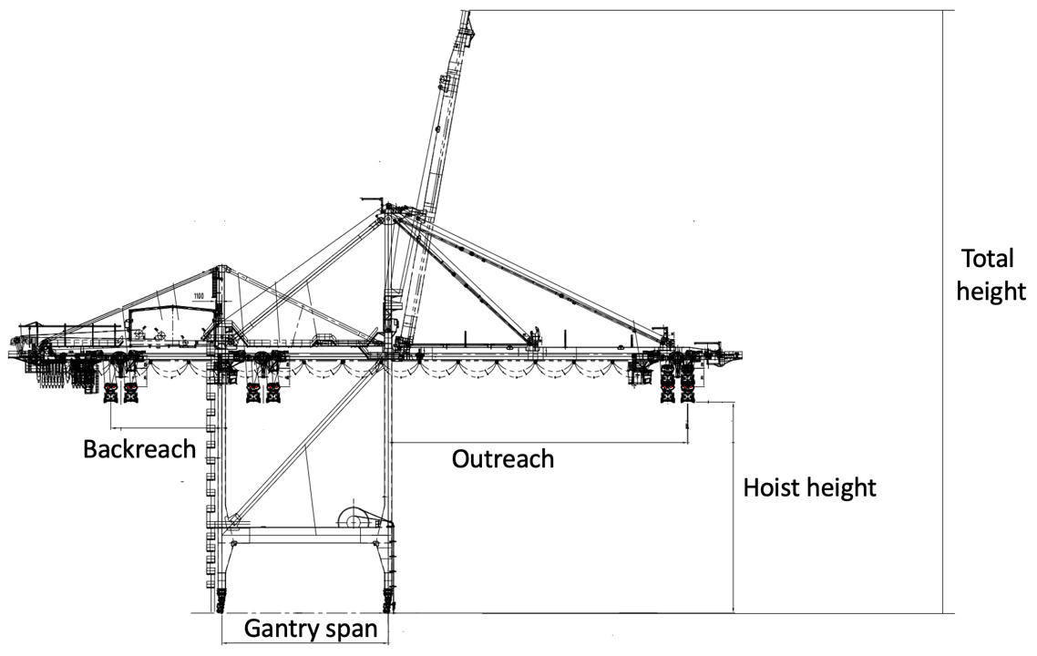
Key dimensions of STS are defined by the technological operations that are provided by the crane. Since STS handles containers from ships to transportational equipment of a container terminal it needs an outreach and hoisting height that will allow to get containers from or to a ship, and a gantry span (or gauge) to provide access of terminal transportation equipment. On most of the ship’s containers are stored on top and under the hatch covers. To handle containers that are transported inside the holds STS needs to have a backreach to remove the hatch covers and store it on the terminal. To provide safe mooring operations STS needs to remove its beam from the port water area. Therefore, STS has the maximum height. Maximum height is also important for STS delivery since some time the cranes need to be transported under the bridges.
The described dimensions are represented in Fig. 1.
Key parameters
Described dimensions are identified by several parameters.
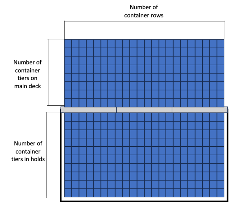
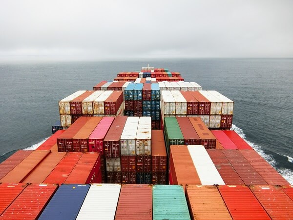
Ships’ dimensions.The main input information for STS dimension is ships’ characteristics: particularly, its width, depth, number of container tiers in holds, number of container tiers on main deck, number of container rows (Fig. 2).
Containerships are classified according to their TEU-capacity, which defines their dimensions. The most popular classification provided by J.P. Rodriguez and T. Notteboom is represented in Fig. 3.
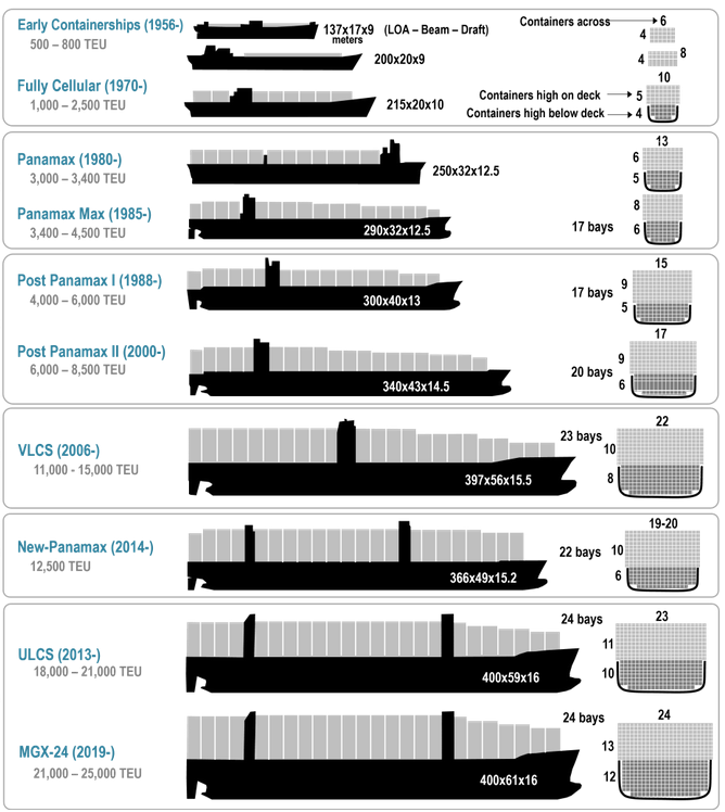
Several publications are dedicated to estimation of ships dimensions according to their deadweight. Particularly, these publications use regression analysis to choose the most suitable ships’ dimension approximation [2]. These approximations can be used to assume the ships characteristics for STS dimensions calculation.
Quay level. As STS is required to get containers from the ships lowest deck, calculation of hoisting height is supposed to include not only ship’s depth, but quay level. Quay level is defined by the wave conditions of the region. The calculation of quay level aims to minimize the number of times, when waves splash on container terminals surface.
Fender width. STS outreach is defined not only by the ship’s dimensions, but also by the dimensions of infrastructural elements, placed on the quay. One of such elements is fender, used to protect quay from ship impact, during mooring operations. A fender’s width might be up to 2,0-2,5 m. Therefore, the calculation of STS outreach should include this value. A fender example is represented in Fig. 4.
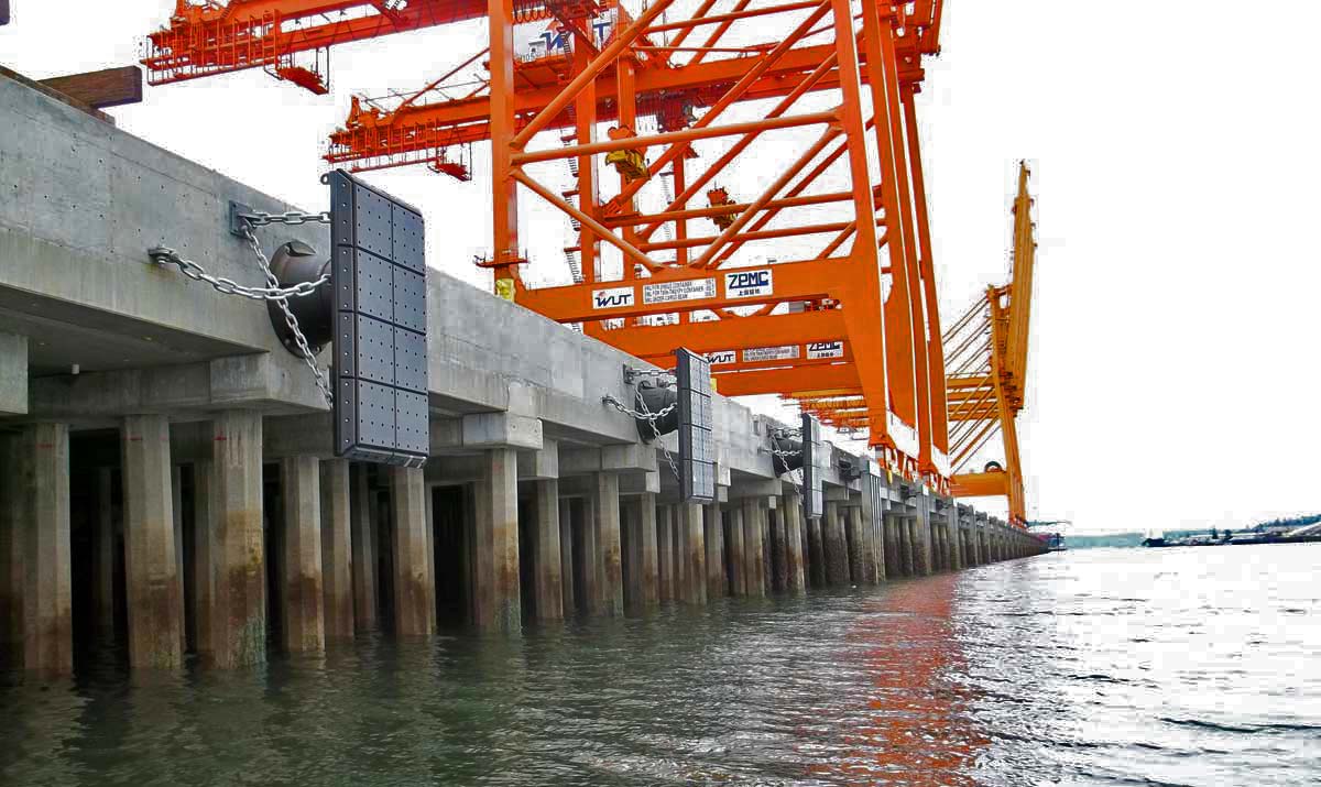
Methods of fender calculations are considered in [5].
Distance from quay line to rail. Another important parameter is distance between STS rail and quay line, which is defined by technological requirements and position of such infrastructural elements as mooring devices, cable channel, water and power supply wells. The technological requirement might include terminal employee passage, road and parking lot for auxiliary transport. Some terminals prefer to save this space for container storage, the other – to provide wider space for mooring teams. Examples of different distances from quay line to STS rail are represented in Fig. 5.
| Antwerp | 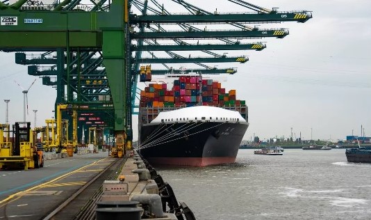 |
| Dubai | 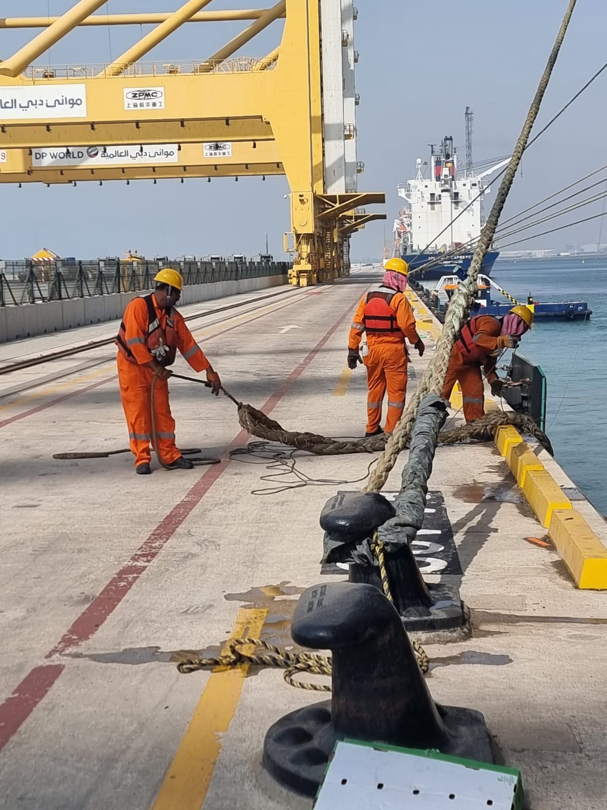 |
There are currently no publications that focus on this distance and consider combination of different engineering decision.
Number of cranes. Crane gantry span is conventionally used for terminal transportation handling. The number of motorways for terminal transport within cranes gantry span is defined by the number of cranes on the quays: each crane needs to have a separate motorway so that terminal transport queues in the motorway under crane that will handle a container but could pass through other cranes.
International labor Organization also suggest installation of terminal employee protected workplace within crane span [6]. This workplace is used by the employees containers’ lashing and unlashing (Fig. 6-7).
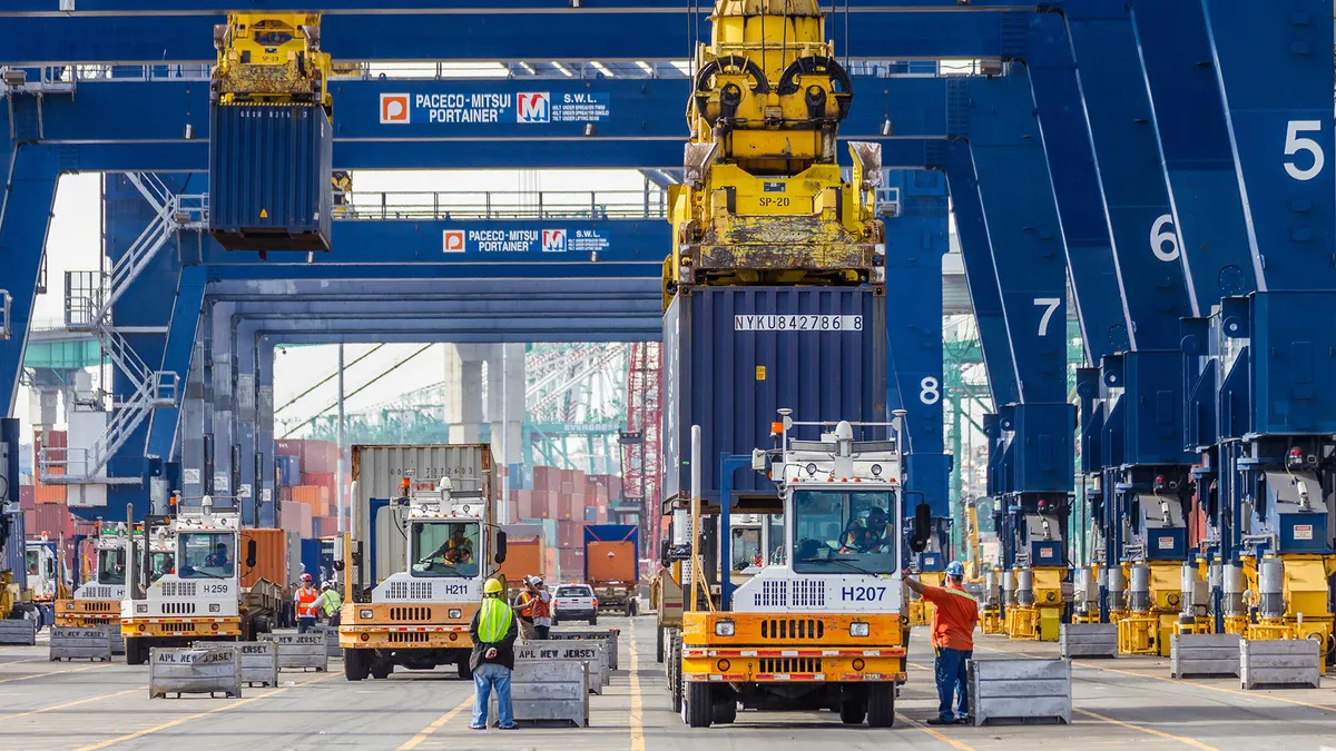
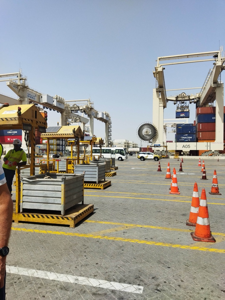
Although this technology is safer, some terminals keep it the old way: employees can walk freely in this area, during work.
The described workplace is not the only possible solution, since STS with two trolleys provide a platform on the crane for lashing and unlashing operations.
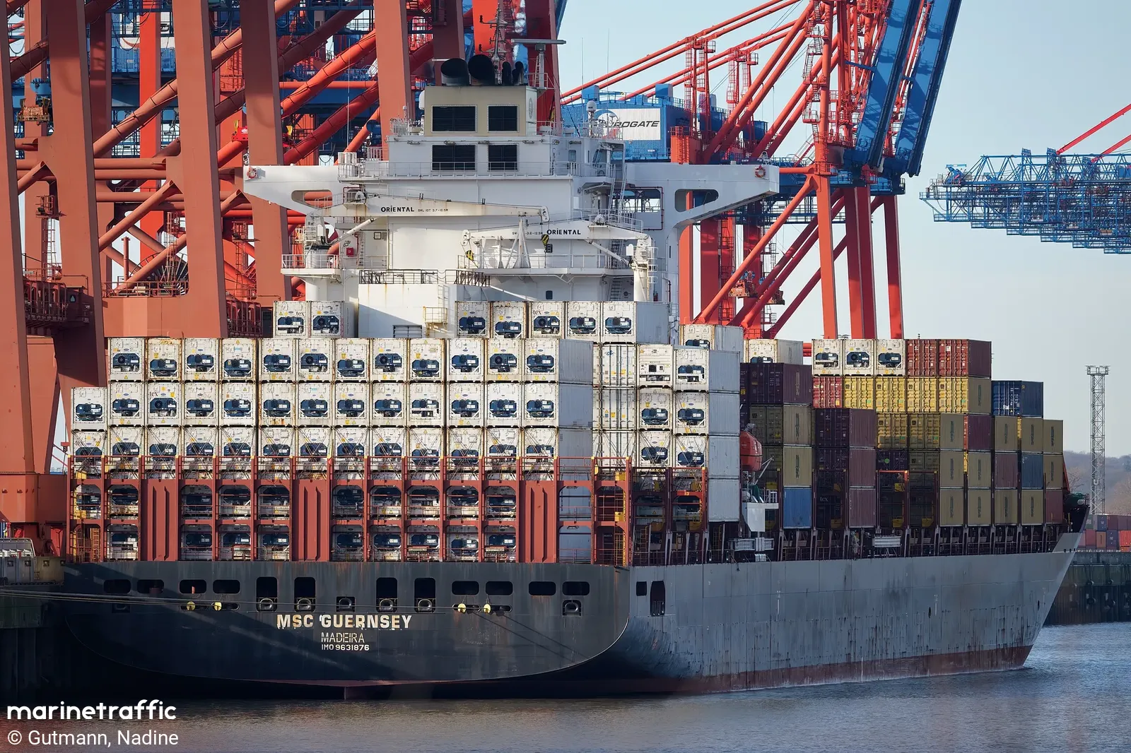
Distribution of container by types. Most of the containers are loaded in one direction, but there are some containers that are places in the opposite direction. Particularly, dry containers are loaded with doors looking to the stern, while refrigerated containers are loaded with doors looking to the bow (Fig. 8-9).
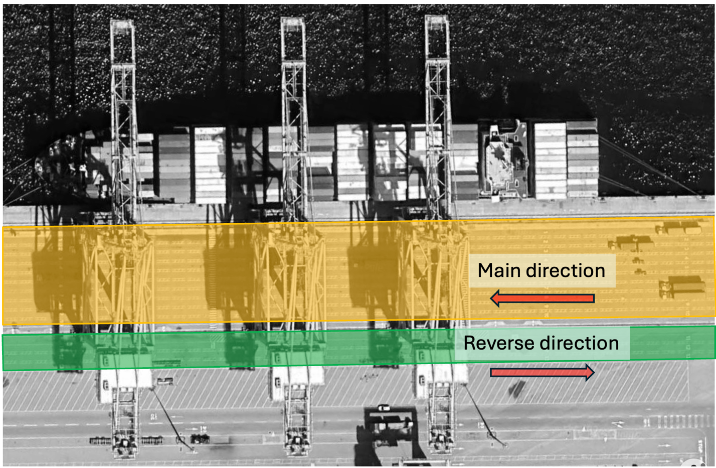
Limited space in quay area might lead to additional intersections of transport flows in different directions. In order to make container handling operation smoother some terminals prefer to set reverse road behind the STS land legs (Fig. 10).
The described parameters are used as input data for the STS dimensions calculation software.
STS configuration
STS configuration includes several technical decisions that will influence STS dimensions.
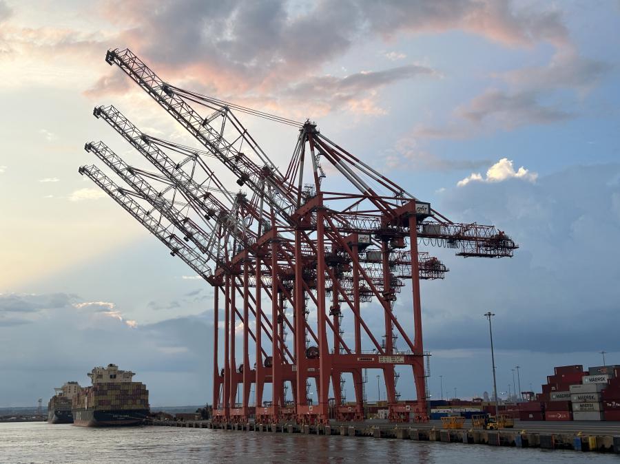
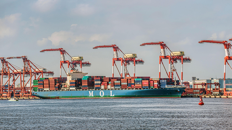
Beam configuration. Conventional beam configuration allows to lift crane’s beam to clear a terminal water area for safe ships’ mooring operations (Fig. 11).
STS total height might influence cities’ architectural rules or civil aviation rules: some cities limit the maximum height of any building or structure in certain areas to save the architectural attractiveness; other areas limit the height of buildings and structures, when an airport is located nearby. Therefore, several manufacturers introduce articulated beam and low profile STS (Fig. 12-13).
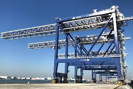
Number of trolleys. Conventional STS cranes have only one trolley that is used to provide container handling operations. Some ports, seeking container handling operations productivity increase, use STS with two trolleys: one is used to transfer containers from ship to transfer platform, another one – from platform to terminal transport equipment (Fig. 14).
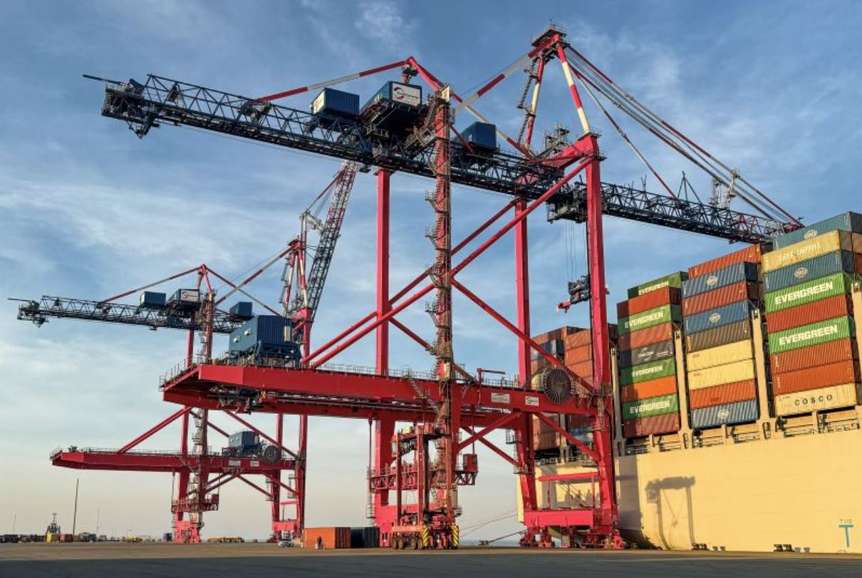
This configuration suggests that hatch covers are stored within gantry span. Therefore, the outreach is defined by the number of quays and cranes. The crane span should be sufficient to place hatch covers and to accommodate car for auxiliary operations.
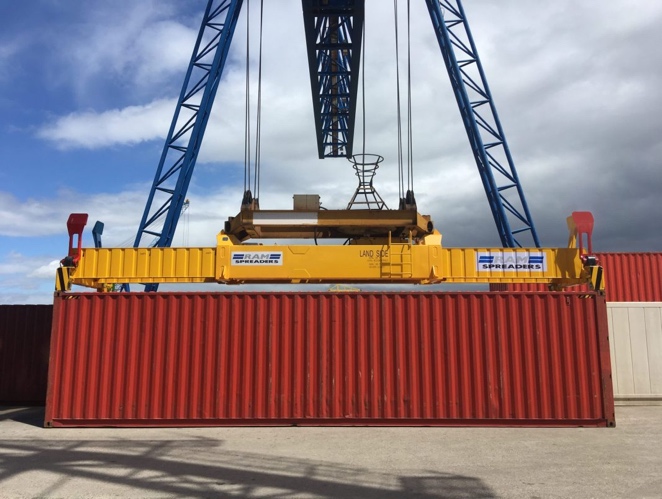
Spreader type. Conventional STS has single lift spreader that can transfer only one box per lift. However, more and more terminals introduce twin-lift and tandem-lift, which can handle up to two and four containers per lift. Each spreader has its own dimensions, which might influence STS overall height. Tab. 1 represents basic information on different types of spreaders.
Table 1. STS container spreader data
| # | Spreader type | General view | Maximum number of containers, TEU/lift |
|---|---|---|---|
| 1 | Single lift |
|
2 |
| 2 | Twin lift |
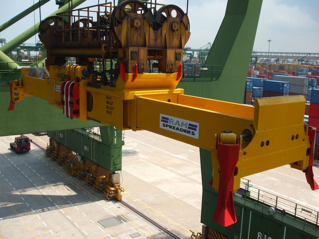
|
2 |
| 1 | Double lift |
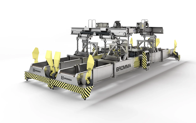
|
4 |
Hatch covers storage. STS backreach is used to remove hatch covers from ships and to temporally place them on the terminal surface (Fig. 15).
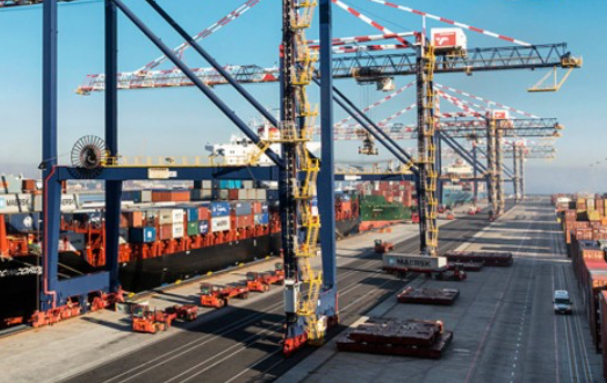
Since area for hatch cover storage is technologically required, but used only for short-term storage, some manufacturers suggest STS with hatch cover support platform (Fig. 17-18).
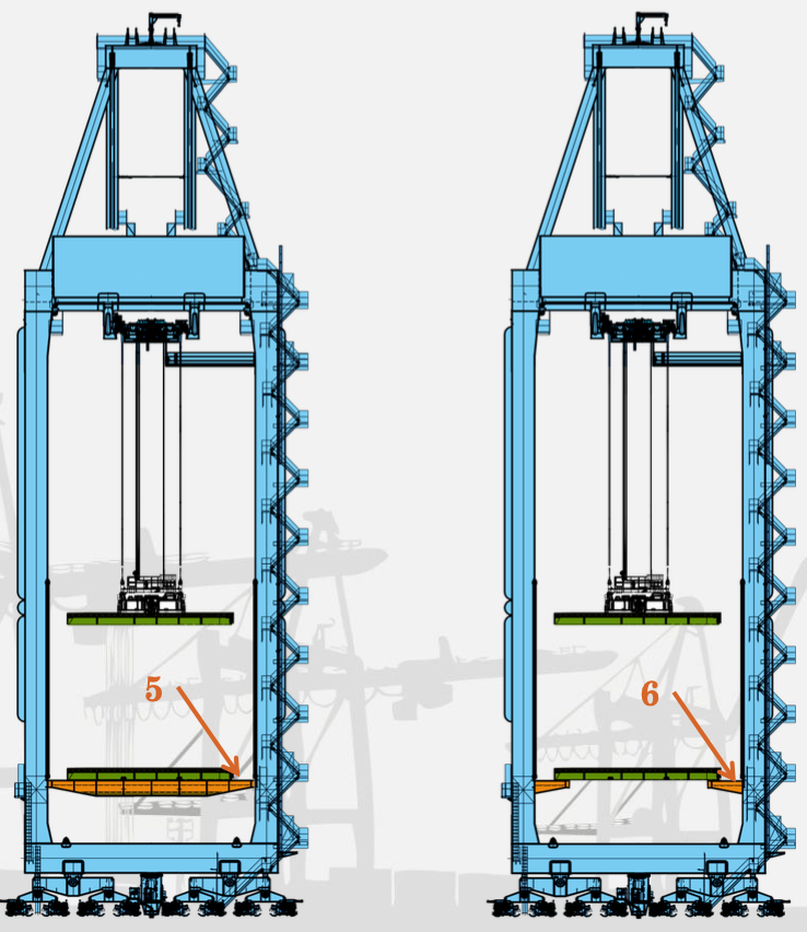
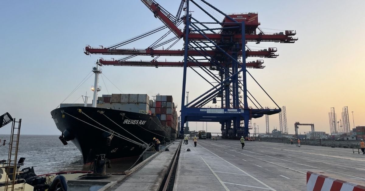
Portal. In most cases, the STS crane portal height is determined by the height of the terminal's transport equipment, which it must accommodate. Different types of terminal transport equipment are represented in Tab. 2.
Table 2. Container terminal transport equipment
| # | Terminal equipment | Length, m | Width, m | Height, m |
|---|---|---|---|---|
| 1 | Terminal tractor and trailer | 17-18 | 2,7 | 3,8-4,3 |
| 2 | Automated Guided Vehicle | 15 | 2,7 | 4,0-4,5 |
| 3 | Straddle Carrier | 10,3 | 4,8 | 10-13 |
Minimum clearance between the transport equipment and STS crane is not defined by a single standard or code, but should not be less than 0,4-0,7 m.
At the same time, there are some terminals, where STS cranes not only provide container handling operations, but also operate as a container yard equipment (Fig. 19).
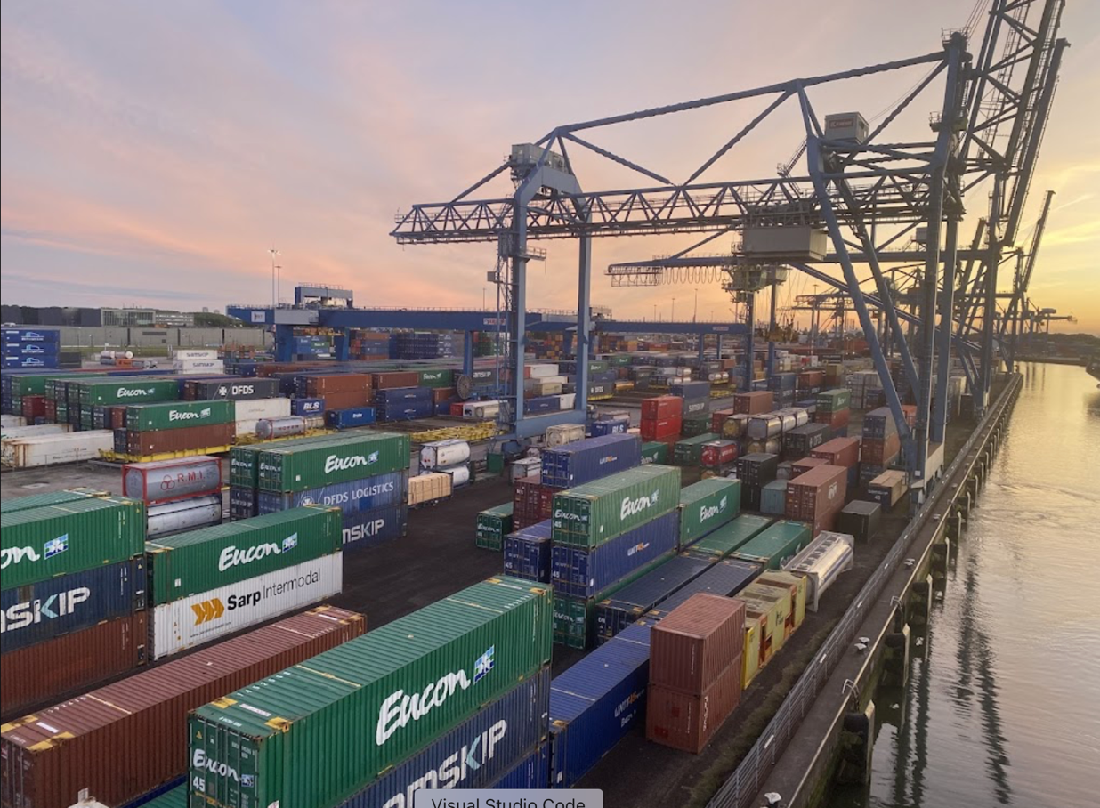
Therefore, the portal might be much wider.
Mathematical relations
The described input parameters and general configurations of STS allow to identify key mathematical relations.
Outreach. Total outreach of an STS is identified by the relation:
where \( W_{ship} \) – ships’ width, m; \( W_{cont} \) – container width, m; \( W_{fender} \) – fenders’ width, m; \( L_{rail} \) – distance between quay line and STS rail, m.
Crane span. STS span is determined by the cranes’ general stability, but should not be less than required number of motorways. The minimum crane span is identified as:
where \( n \) – number of cranes on a quay; \( W_{road} \) – motorway width, m; \( W_{work} \) – employees’ workplace width, m;
There are several ‘standard’ or typical gauges in the industry. However, for every project the crane span can be selected individually.
Backreach. Backreach is identified as:
where \( W_{hatch} \) - width of hatch cover storage area, m; \( W_{back\_road} \) – width of driveway behind a crane, m.
Most of hatch covers are 12-15 meters width [8].
Hoisting height. Hoisting height calculations consider high and low tides:
Where P_{high_tide} – high tide level, m; S_{freeboard} – ships’ freeboard, m;S_{conts} – number of containers on main deck, cont; P_{low_tide} – low tide level, m; S_{depth} - ship’s depth, m; S_{move} – ship’s movement distance due to waves influence, m.
Portal height. Portal height is defined by the relation:
where H_{equip} – terminal transport equipment height, m; h - safety clearance between transport equipment and STS, m.
Total height. For early stages of STS design this parameter can only be roughly estimated. For the conventional STS the total height is estimated as the outreach, rotated on 70-80o:
Where \(H_{beam} \) – boom height, m;\(α \) – stowed boom angle, m.
This formula is correct for the local coordinates.
Therefore, STS total height:
Software tool for STS drafting
The described parameters and relations are used as input data for developed STS dimensions calculation software. The main aim of the software is to generate comprehensive technical assignment that will improve the communication between port operator and equipment manufacturer. Although manufacturers provide different contracts, it is significant for the port operator to understand the questions that might arise during the process of STS acquisition.
Main screen of the software is represented in Fig. 20.
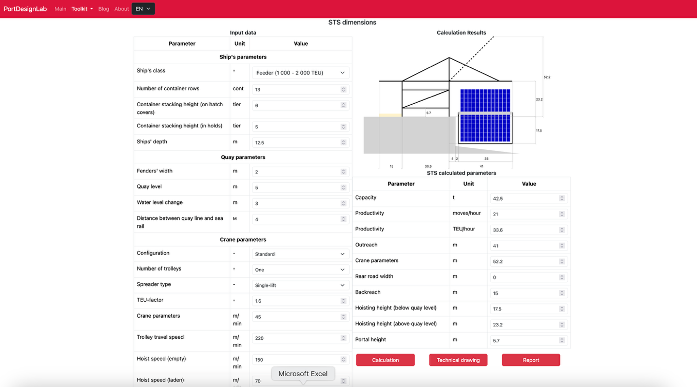
The screen includes:
- input data that is required to calculate STS dimensions (Fig. 21);
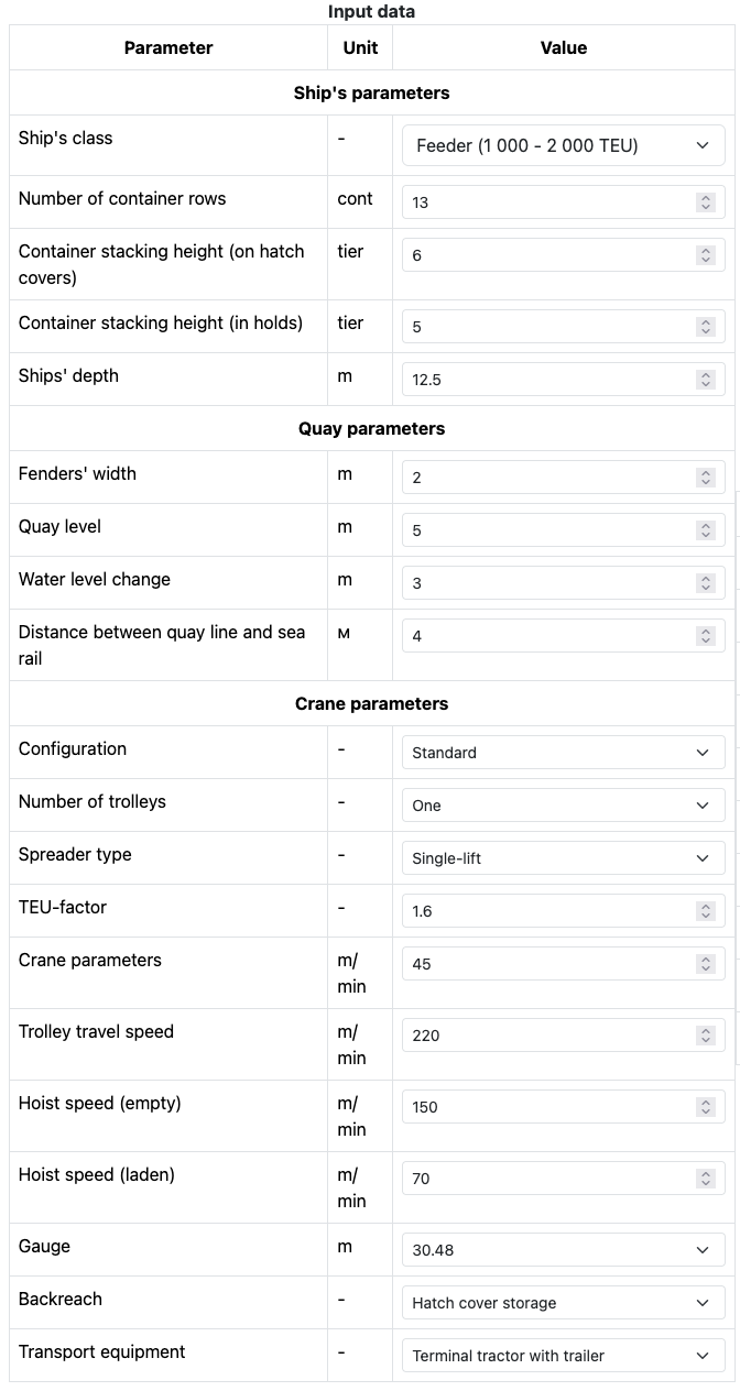
- calculation results (Fig. 22);
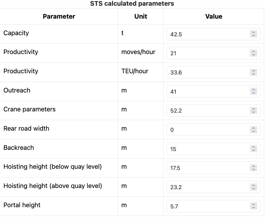
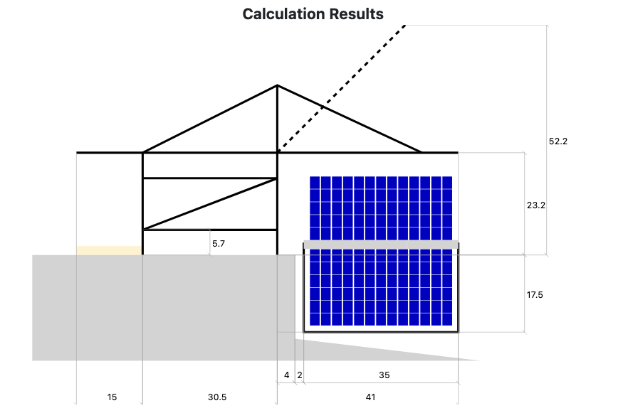
- STS technological scheme with all the dimensions (Fig.23).
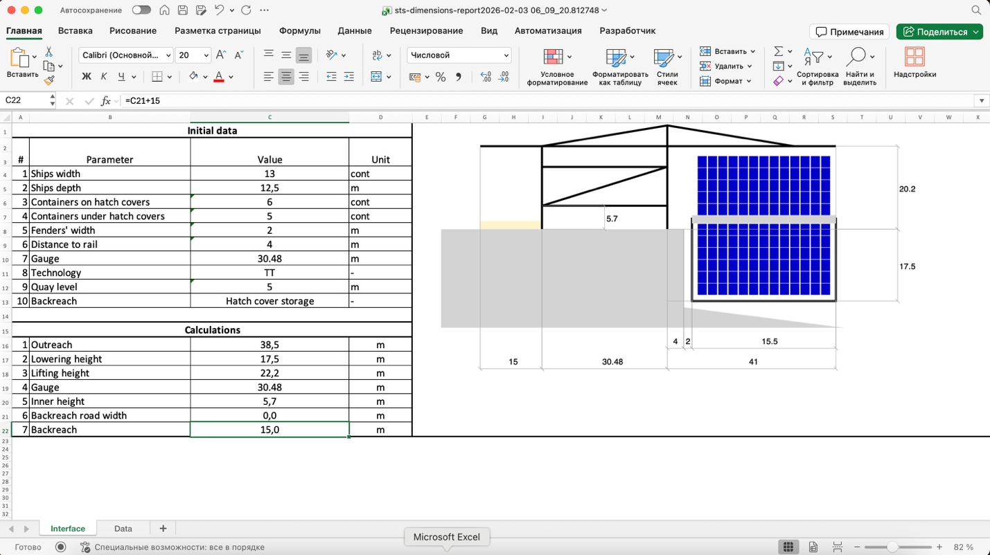
The calculation results can be exported into a spreadsheet with calculations and scheme and into technical assignment (Fig. 24).
Moreover, the results can be exported into a CAD-suitable format (particularly, DXF) so that it can be used in technical drawings of container terminals.
References
- Jean-Paul Rodrigue. The Geography of Transport Systems - 2024, New York: Routledge, 402 p. URL: https://transportgeography.org/contents/chapter5/maritime-transportation/evolution-containerships-classes/
- PIANC. MarCom WG 235. Ship Dimensions and Data for Design of Marine Infrastructure, 55 p.
- Carl A. Thoresen. Port Designer’s Handbook. – 2014, 607 p.
- G. P. Tsinker. Port Engineering. - 2004, 881 p.
- PIANC. MarCom WG 211. Fender Guidelines. – 2024, 219 p.
- ILO. Safety and health in ports. – 2005, 527 p. URL: https://www.imo.org/en/ourwork/facilitation/pages/ilocode-default.aspx
- Hatch Cover Support Platform. URL: https://www.gbportinnovations.com
- PIANC. MarCom WG 135. Design Principles for Small and Medium Marine Container Terminals. – 2014, 135 p.