Introduction
3D visualization is an effective tool for communicating container terminal design decisions to clients, stakeholders, and project teams. However, most design results are produced as 2D technical drawings in DXF format, and converting them into a 3D model typically requires significant time and specialized knowledge of computer graphics software. This article presents a method for automatically generating a 3D terminal model directly from a 2D DXF drawing. The software classifies drawing layers, calculates 3D geometry for each object type, and renders the result interactively in a web browser using Three.js [1]. The generated model can be exported to GLTF format [2] for use in presentations, animations, or further editing.
Algorithm description
A container terminal general layout typically consists of several object types: terminal limits, buildings, containers, equipment, railways, and traffic routes. Most of the time these objects are included to different layers of CAD technical drawing. However, the names of the layers will differ from drawing to drawing. Therefore, the first step of 3D model creation is classification of layers: each layer is classified by user as one of the possible types of objects.
The next step is to calculate 3D geometry parameters for each object type, as each requires a different approach.
Terminal limits are rarely of rectangular form. They are usually represented as a polygon of complicated form. That means that to calculate terminal surface it is necessary to triangulate this polygon (Fig. 1). Triangle is the fundamental surface primitive in real-time 3D renderers, as any polygon surface can be decomposed into triangles [3].
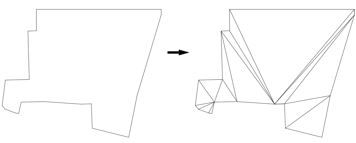
To triangulate a polygon, an ear-clipping algorithm is applied [4]. The algorithm iterates over polygon vertices. At each step, a group of three consecutive vertices is tested as a candidate ear: the middle vertex must be convex, and no other polygon vertex may lie inside the formed triangle. If both conditions are met, the triangle is recorded and the middle vertex is removed from the polygon. The process repeats on the reduced polygon until only one triangle remains.
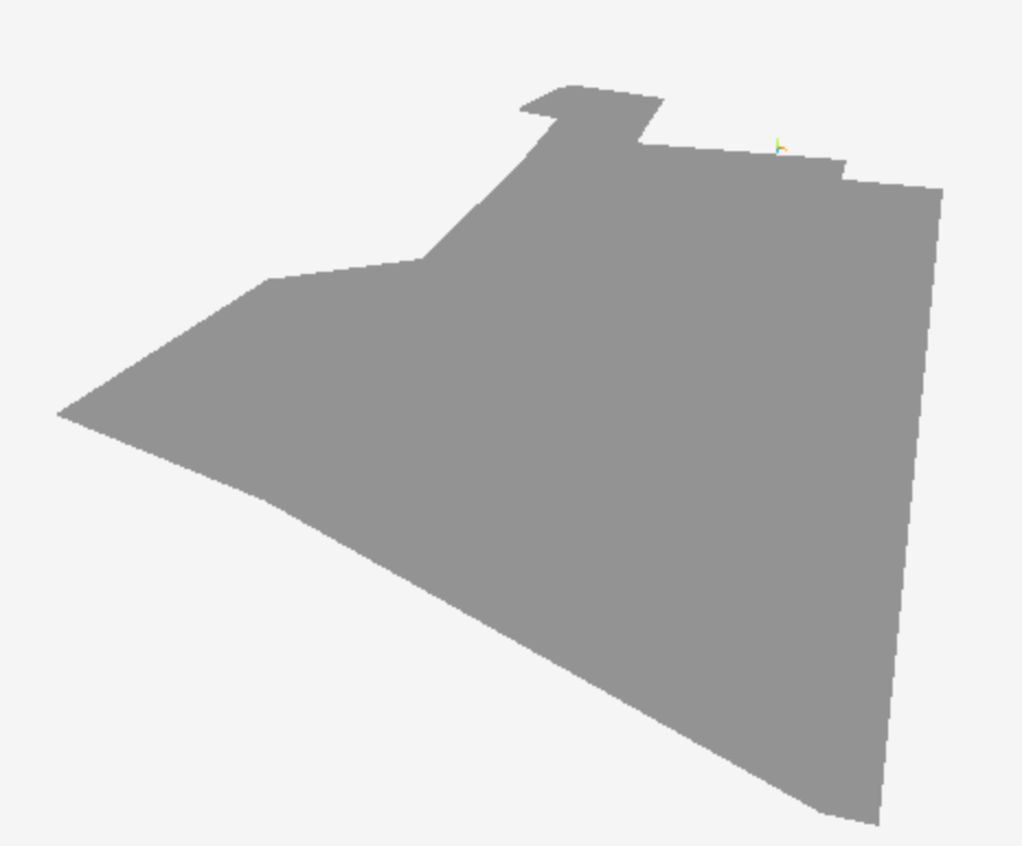
The result of the algorithm is multidimensional list of polygon vertices. Each sub-list represents a triangle that needs to be represented on a 3D model (Fig. 2)
A container can be represented as a rectangular box with length 6.06 m, width 2.44 m, and height 2.6 m, decomposed into triangles for rendering. However, rendering individual containers at yard scale requires significant computational resources. Therefore, the software renders container stacks rather than individual containers (Fig. 3).
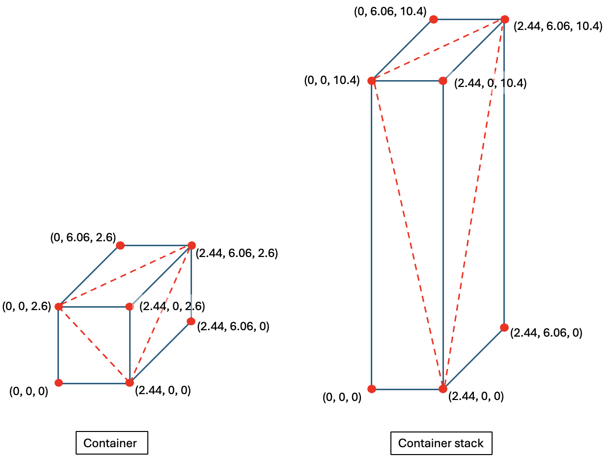
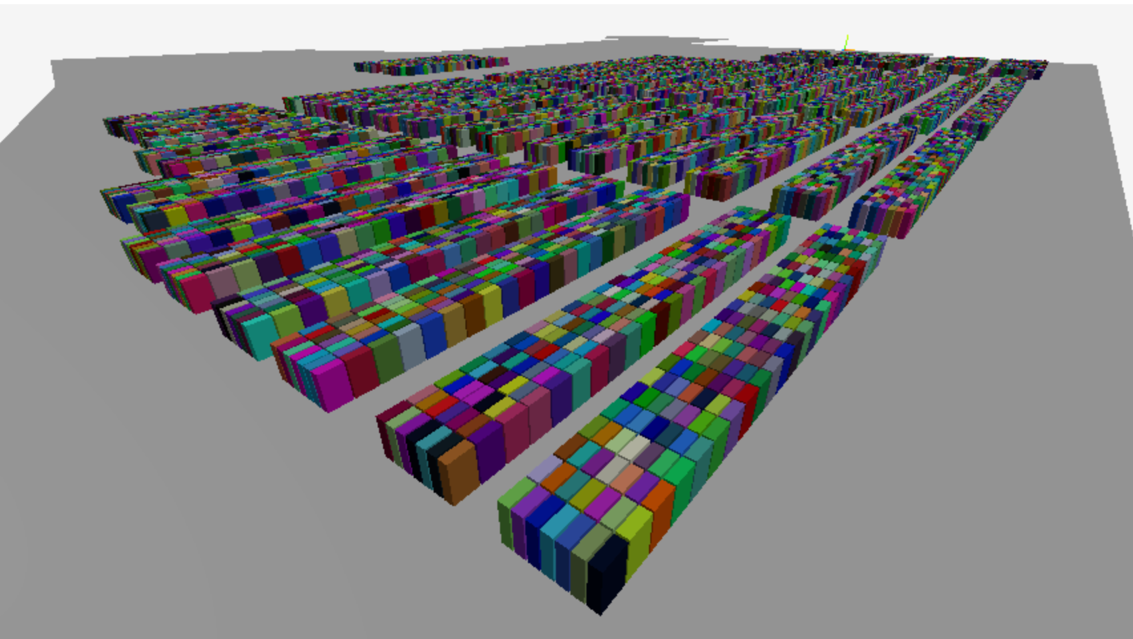
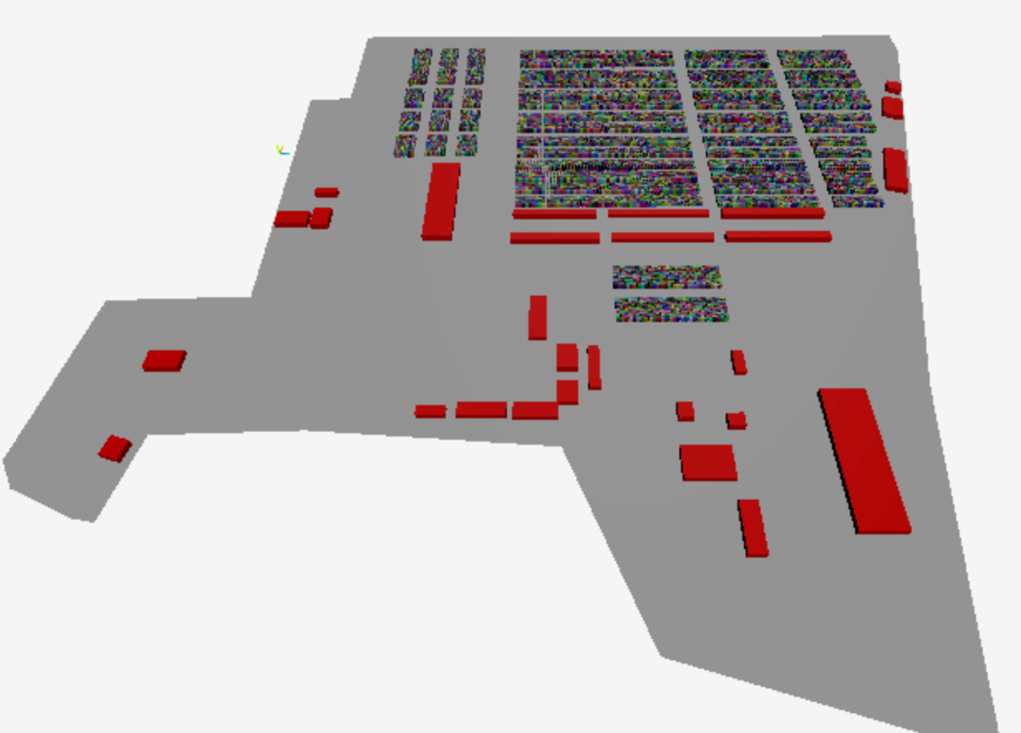
Fig. 4 represents an example of generated container yard.
Buildings’ architectural design differs from project to project and from organization to organization. Since architectural design varies widely between projects, the tool supports both importing existing building models and generating simple cubic placeholders suitable for early-stage visualization. Such representation might be enough for the early stages of the project or for the purposes of company marketing (Fig. 5).
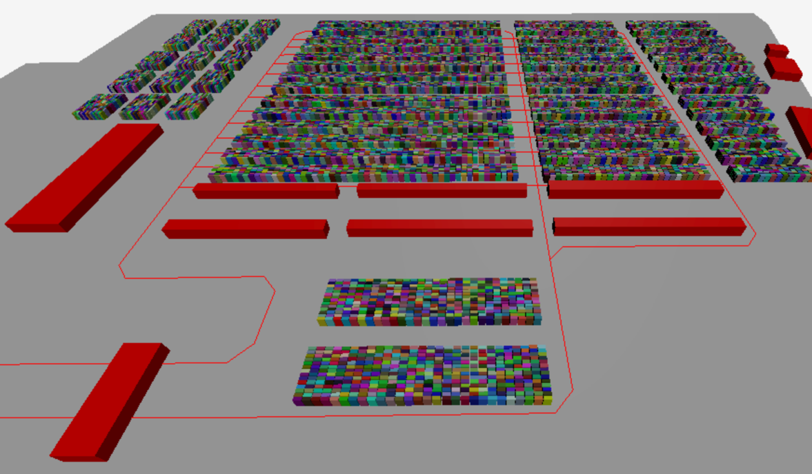
Roads and traffic routes for the purposes of visualization can be represented as polylines on the terminal surface. Lines are a fundamental graphics primitive in 3D renderers, natively supported by WebGL without requiring triangulation [5]. Fig. 6 represents an example of road on a terminal surface.
Container terminal equipment has many details and complicated logic of dimensions calculation. Therefore, to represent container handling equipment special models were developed (Fig. 7). The models are loaded into the Three.js renderer as is.
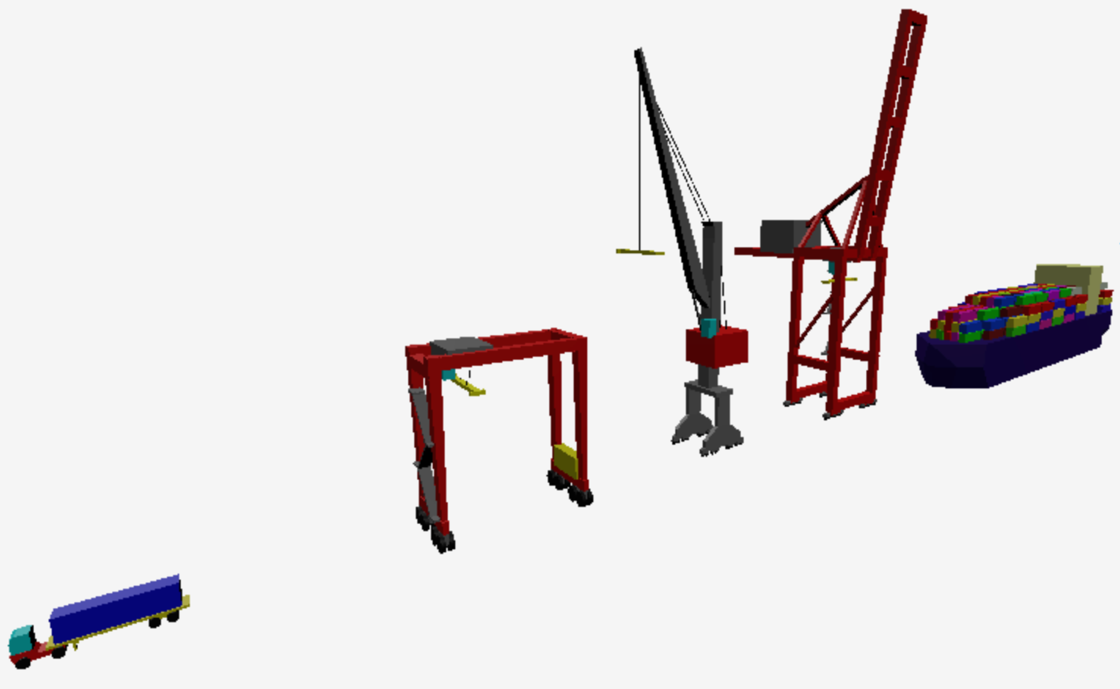
The only requirement for model import is that the equipment insertion point in the 2D drawing must match the origin point of the corresponding 3D model.
Software interface
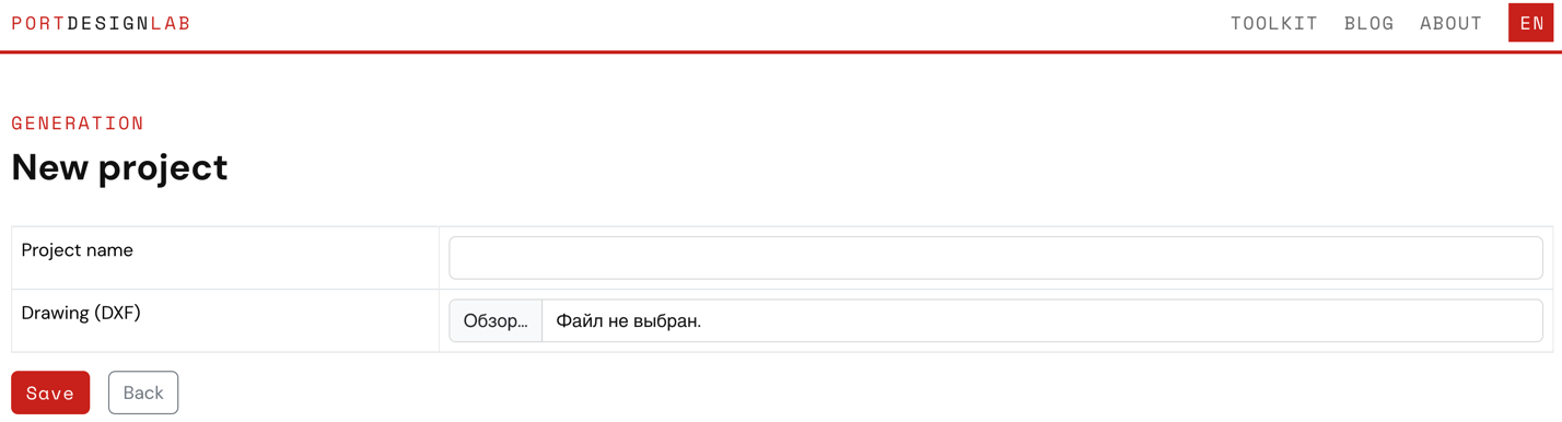
The described algorithm is implemented as a web-based tool available on the PortDesignLab website. To start, the user imports a DXF file through the project creation interface (Fig. 8).
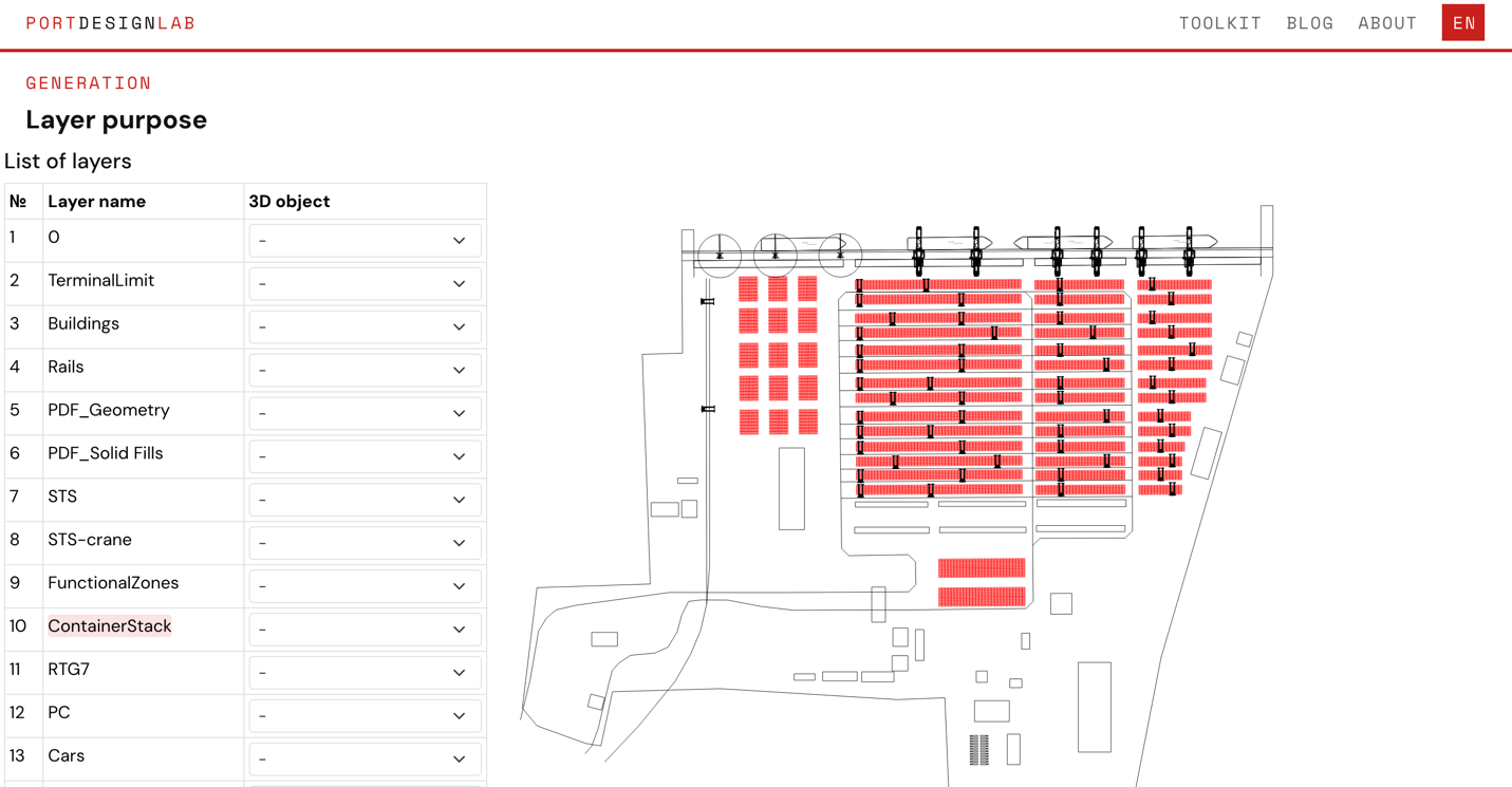
The software parses DXF file and returns list of model layers and its SVG representation. By hovering a model layer, user highlights elements that are correlated with this layer. The object type is selected from the list behind model layer name (Fig. 9).
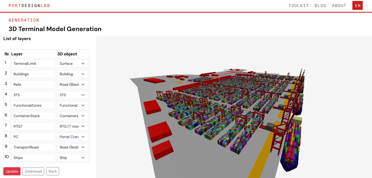
The next step returns generated 3D model (Fig. 10). The model can be downloaded in GLTF format.
Conclusion
The described software significantly reduces the time required to produce a 3D visualization of a container terminal from an existing DXF drawing. It can be applied at early design stages for internal design review, at concept stage for client presentations, and for simulation model preparation. Unlike building a 3D model from scratch, the tool requires no specialized knowledge of computer graphics — only a correctly layered DXF file as input. The further development steps are: generating 2D cross-sections of the terminal for design documentation, and exporting BIM-suitable file formats (particularly IFC) for import into BIM editors. The tool is available at: https://portdesigntoolkit.pro/model-generation/.
References
- Three.js – JavaScript 3D Library. URL: https://threejs.org/
- glTF. The 3D Asset Delivery Format. URL: https://www.khronos.org/gltf/
- Shirley P., Marschner S. Fundamentals of Computer Graphics. A K Peters/CRC Press, 2015.
- Elberly D. Ear clipping algorithm. Triangulation by Ear Clipping. URL: https://www.geometrictools.com/Documentation/TriangulationByEarClipping.pdf
- WebGL 1.0 Specification. URL: https://www.khronos.org/registry/webgl/specs/latest/1.0/