Introduction
Designing a bulk cargo yard starts with one question: how much material must the yard hold, and what stockpiles on a limited storage area will deliver that capacity? The Bulk Cargo Stockpile Generator, a web tool on PortDesignLab, answers it in seconds: it calculates the capacity of a single coal or other bulk stockpile and generates its drawing (DXF) and 3D model.
Storage capacity and stockpile layout are among the first technological design decisions in a port terminal project. Their results feed the later stages: the general plan, the choice of yard pavement, storm drainage, utility routing, and the design of handling equipment such as stackers and reclaimers, including boom parameters and travel mechanisms.
In practice the layout is prepared in several variants to find the best use of the available area. Each variant requires repeated calculations and drawing work, which is slow and needs experience. Changes in global supply chains have increased the number of terminal development projects, so automating this routine step is increasingly relevant.
The literature on yard capacity is mostly about inventory theory and Monte Carlo simulation [1–5], which estimate how much storage is needed under stochastic vessel sizes, storage times and berth productivity. Far fewer works address the geometry of an individual stockpile. Those that do often approximate it with simple solids and ignore storage technology, material properties, and how the pile is built and reclaimed [6]. Commercial particle-based software exists [7, 8], but it is costly and, for many designers, hard to obtain. The tool described here is a web-based alternative focused on the design stage.
Stockpile types and cross-section
A bulk cargo yard consists of individual stockpiles, each open or covered. By plan shape, the tool distinguishes two types, both used for coal and other bulk materials:
- Pyramidal stockpile (the tool's label; also called longitudinal or linear). An elongated pile with sloped sides and conical ends. A covered pile of this type can be divided into sections, one per material.
- Radial stockpile (laid along a circular arc). It holds one material at a time, so a yard with several materials uses several radial piles.
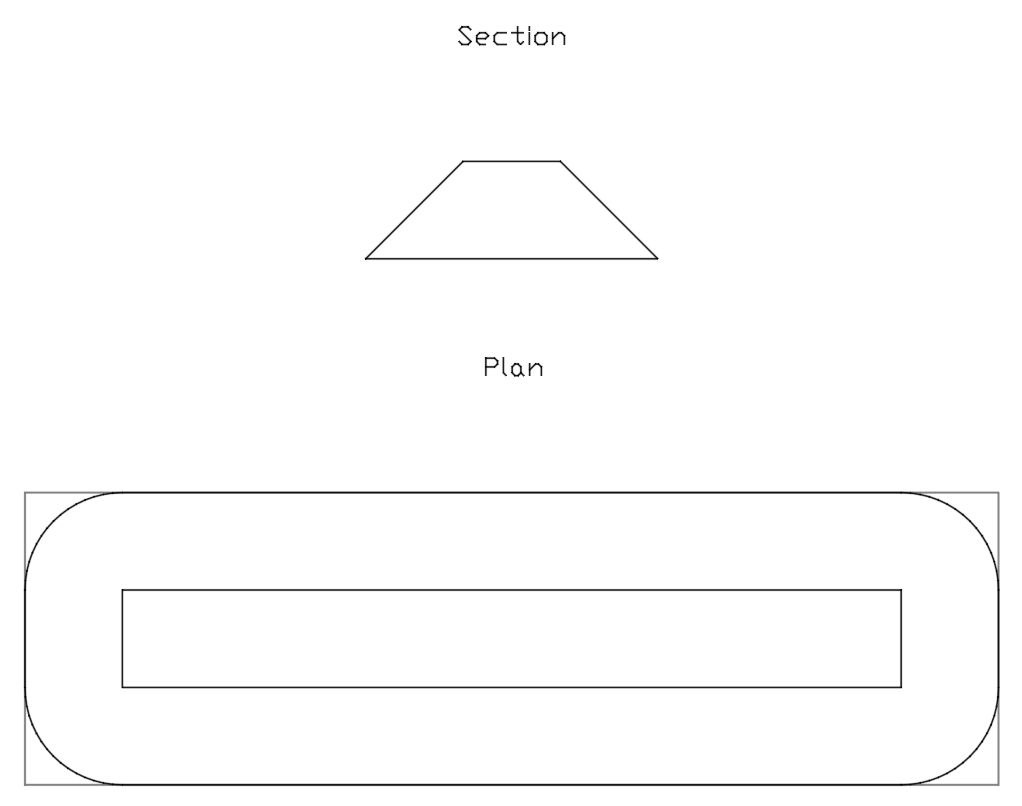
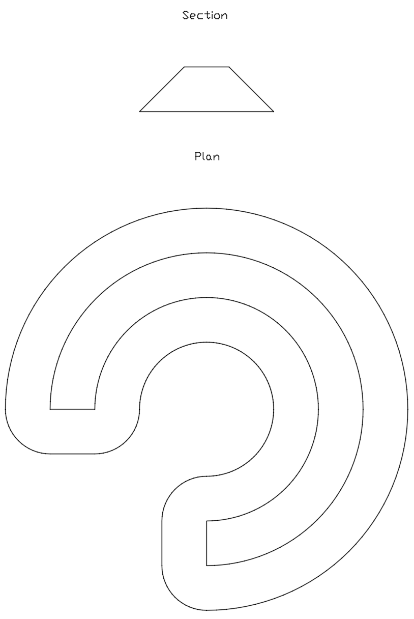
The cross-section of a pile depends on the angle of repose of the material, the permitted storage height, and the pile width. The geometry is decided by one comparison. For a pile of base width w and angle of repose γ, the apex height of the triangular profile is
If ht does not exceed the permitted storage height hmax, the cross-section is a triangle and the pile height is h = ht. Otherwise the pile is truncated at the permitted height, the cross-section is a trapezoid, and h = hmax. In both cases h denotes the actual pile height used in all formulas below. The horizontal run of each slope is
Two design features change the capacity of the same footprint:
-
Retaining walls on one or both sides, and at the ends, allow material to be piled more steeply than its natural slope, which raises capacity. Their height and inclination are inputs.
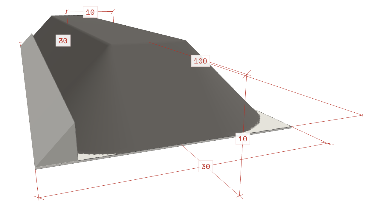
Figure 3. Retaining walls -
Recessed floors (a pile set into a recess with slopes) keep material from spilling onto the travel path of stackers and reclaimers.
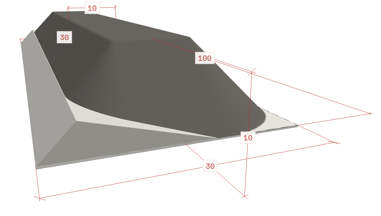
Figure 4. Recessed floors
At the ends, an open yard pile is normally unrestricted and finishes in a cone. A pile bounded by end walls, typical for covered yards with sections, has a different plan outline.
Capacity formulas
Notation: w is the pile width at the base, L the overall length of the base outline, h the actual pile height and r the slope run defined above. The stockpile volume is the sum of three parts: the prismatic body, the end wedges (trapezoidal piles only) and the corner cone.
The body is the cross-section area S multiplied by its length. Because the overall length L includes the end slopes, the body length is L − 2r:
The cross-section area is found by subtracting from the full profile the parts displaced by the retaining walls. The inputs are the pile height h, the angle of repose γ, the pile width w, the wall heights hL and hR, and the wall inclinations δL and δR, measured from the vertical (δ = 0 is a vertical wall). A wall must not be higher than the pile. For a triangular profile:
For a trapezoidal profile, the full triangle is replaced by the truncated profile and the same wall terms are subtracted:
At each end of a trapezoidal pile, the slope forms a wedge across the flat top. Together with the four corners of the pile, which are quarter-cones of base radius r and height h, the end volumes are:
Vcone = (1/3) · π · r² · h
For a triangular pile, r = w / 2 and the cone reduces to the familiar (1/3)π(w/2)²h. For a trapezoidal pile it does not: the corner radius is r, not w / 2.
For a radial pile of arc angle α (degrees), the body length is the arc length at the radius of the cross-section centroid Rc (Pappus's theorem). With walls, the centroid shifts away from mid-width, so Rc must be corrected accordingly:
End walls. An end wall of height hE cuts off part of the end cone. The source method approximates the removed part as half of an ellipsoid:
This is an approximation. The cut-off part of a cone is not exactly an ellipsoid segment, and the expression has no wall position parameter. It also becomes unphysical for tall walls: for w = 30 m, γ = 35° and hE = h = 10.5 m it gives a negative end volume. Use it only for end walls well below the pile height and check such cases against the 3D model volume.
Finally, the storage capacity in tonnes is the volume multiplied by the bulk density of the material:
From formulas to drawings and 3D
The same parameters drive the geometry of the drawing. The tool computes the coordinates of the pile outline relative to a base point (0, 0). For a pyramidal pile of overall length L and width W, the outline is a rectangle with four rounded corners. Each corner is a quarter-circle arc of radius equal to the slope run, approximated by a polyline of 20 segments. The arcs and the four inner corner points are then joined into polylines and written to a DXF file using the Python library ezdxf [9]. DXF is a CAD exchange format with a published specification, so the drawing can be opened in common CAD packages and used in a general arrangement plan.
Two details make the output useful for real layouts:
-
End walls. When retaining walls are placed at the pile ends, the outline is clipped. Arc points that fall beyond the distance from the theoretical pile edge to the wall are not drawn.
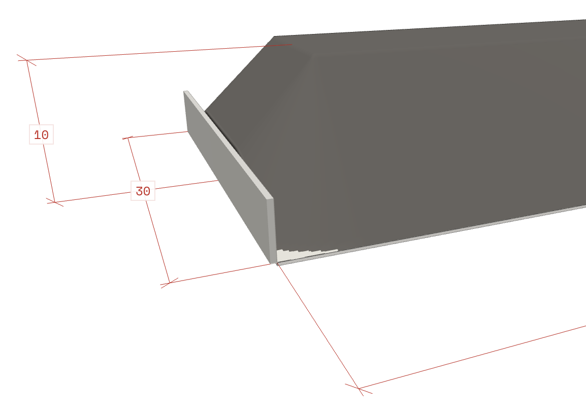
Figure 5. End walls -
Sections. When a pile is divided into several sections, each is generated for a length of L / N, where N is the number of sections. Sections allow different materials to share one covered pile.
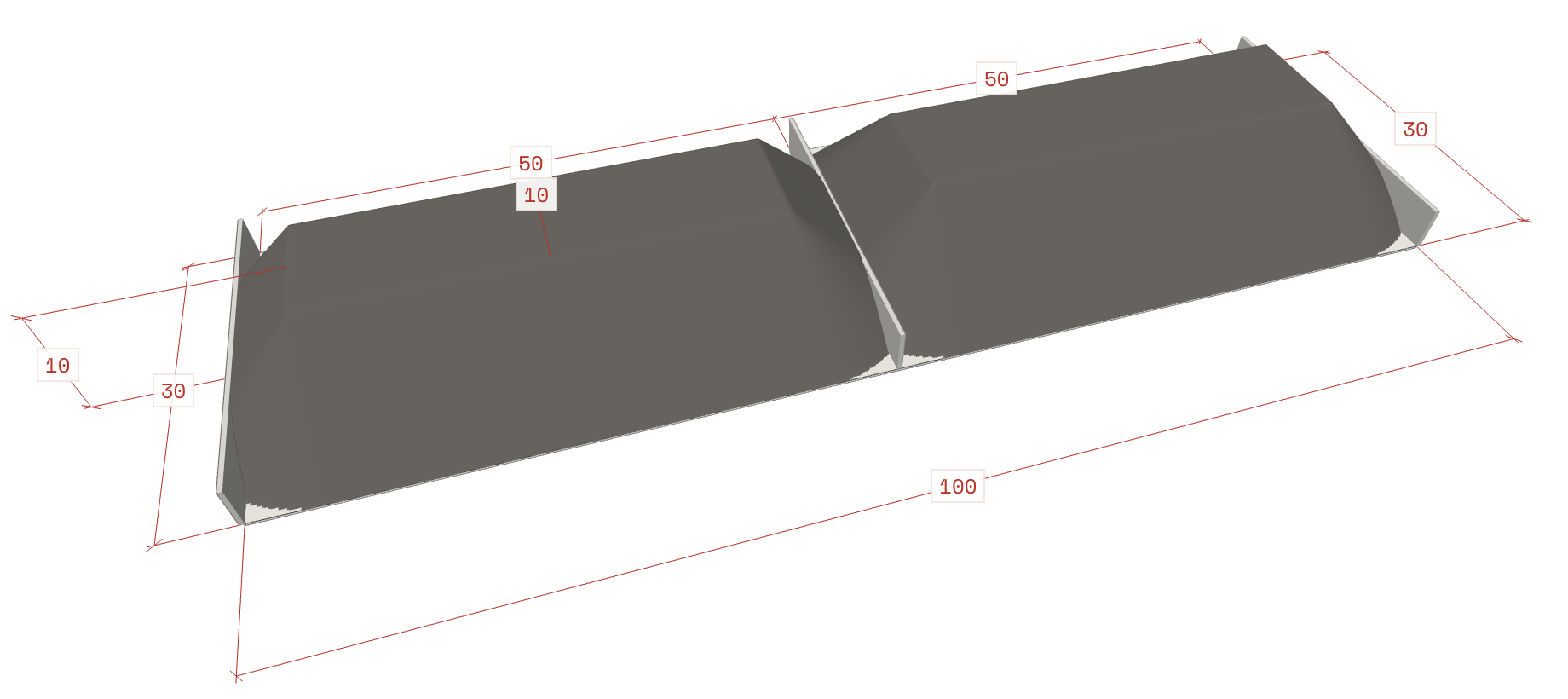
Figure 6. Sections
Adding the height to the plan coordinates turns the same outline into a three-dimensional model. The 3D view helps to check the result visually and to present variants to colleagues and clients.
Volume from the 3D model
The 3D model is not only a picture. Because it is a closed surface, its volume can be computed independently of the analytical formulas and used to check them.
- Build a closed triangulated surface: the top and side faces of the pile plus a flat base cap, with all triangle normals pointing outward. Retaining walls are not material and are left out.
- Sum signed tetrahedra. For every triangle with vertices v0, v1, v2, take the volume of the tetrahedron it forms with a fixed origin. This is the divergence theorem applied to the mesh and is exact for flat triangles:
For a pile standing on a flat base, a simpler form gives the same result: sum, over the top-surface triangles, the projected plan area multiplied by the mean height of the three vertices:
The capacity then follows as M = V · ρbulk. The mesh must be watertight and consistently oriented, otherwise the sum is wrong. Discretisation also matters: approximating each full circle with 80 segments, as the 20-segment quarter arcs do, loses about 0.07% of the volume of a cone, which is negligible.
As a check of the formulas above, the volume of piles with rounded-corner footprints was also integrated numerically over a fine grid of the pile surface. The corrected formulas agree with it exactly, while the common shortcut of multiplying the overall length by the cross-section and adding a cone of base radius w / 2 overestimates the volume:
| Pile | 3D integration, m³ | Formulas above, m³ | Shortcut, m³ |
|---|---|---|---|
| Triangular: L = 200 m, w = 30 m, γ = 35° | 29,257 | 29,258 | 33,984 (+16%) |
| Trapezoidal: L = 200 m, w = 30 m, γ = 35°, hmax = 6 m | 24,636 | 24,636 | 27,131 (+10%) |
| Trapezoidal: L = 200 m, w = 40 m, γ = 38°, hmax = 8 m | 45,218 | 45,218 | 50,968 (+13%) |
Using the tool
The Bulk Cargo Stockpile Generator runs in the browser, and the interface has an English language switch. The user fills in four groups of parameters:
| Group | Inputs |
|---|---|
| Cargo | Bulk density (t/m³), angle of repose (degrees) |
| Stockpile | Type (pyramidal or radial), storage area length and width (m), allowable storage height (m), number of sections |
| Clearances (labelled "Reserves" in the interface) | Clearance on the right side, left side and end of the pile, end-side service zone (m) |
| Retaining walls | Height and angle of the left and right walls, height of the end wall (m) |
The tool returns the key results of the calculation:
- storage capacity (t);
- stockpile volume (m³);
- actual stockpile height (m);
- base area (m²).
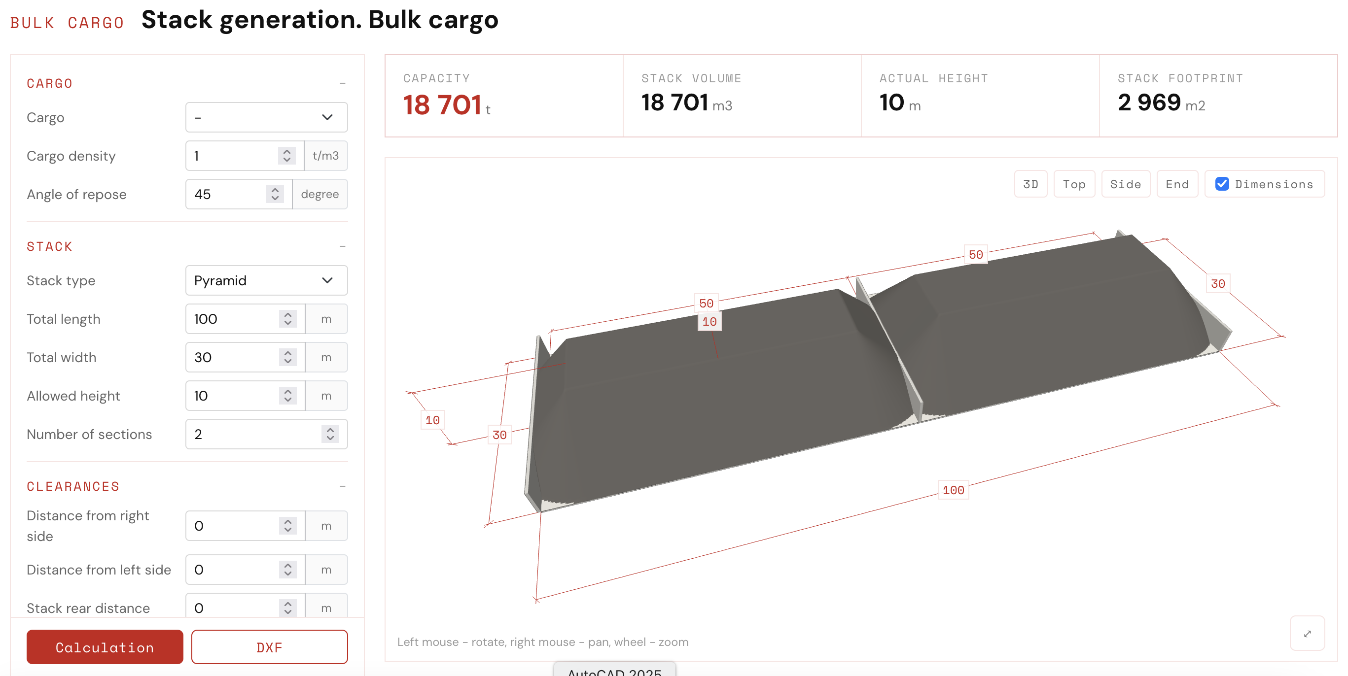
The results are shown in the Dimensions panel, which displays the geometry in four views: 3D, top, side and end. The 3D view is controlled with the mouse (left button to rotate, right button to pan, wheel to zoom) or by touch (one finger to rotate, two fingers to zoom and pan). A DXF button exports the drawing.
A typical workflow is short. The designer enters the cargo properties, sets the storage area dimensions and the height limit, and checks the capacity. If the capacity is too low or the pile does not fit, they change the height, add walls or sections and recalculate. When a variant is acceptable, they export the DXF and place it in the terminal plan.
Conclusion
The Bulk Cargo Stockpile Generator turns the stockpile calculation into a quick, repeatable step. It accounts for the storage technology, namely stockpile type, cross-section shape, retaining walls and sections, and outputs both the capacity and a drawing that is ready to use. This reduces the effort needed to prepare layout variants for new ports and for the modernisation of existing yards. Because the volume can also be computed from the 3D model, every result can be cross-checked against the analytical formulas.
The output can be used to assemble general arrangement plans of terminals with different stockpile configurations, and to prepare terms of reference for the design of handling equipment, yard pavement and utility networks.
The tool is available on the PortDesignLab website: Bulk Cargo Stockpile Generator.
References
- Kuznetsov A.L., Galin A.V., Valkova S.S., Sampiev A.M. Calculation of the capacity of a bulk cargo warehouse at a seaport using simulation modeling. Bulletin of ASTU. Series: Marine Engineering and Technology, 2022, No. 3, pp. 82-89.
- Bassan S. Evaluating seaport operation and capacity analysis: preliminary methodology. Maritime Policy & Management, 2007, Vol. 34, No. 1, pp. 3-19.
- Valkova S.S. Probability-statistical method for calculating the capacity of a seaport warehouse. Bulletin of the Admiral S.O. Makarov State University of Maritime and Inland Shipping, 2018, Vol. 10, No. 3, pp. 507-519.
- Rushton A., Croucher P., Baker P. The Handbook of Logistics and Distribution Management: Understanding the Supply Chain. Kogan Page, 2022.
- Kuznetsov A.L., Kirichenko A.V., Semenov A.D. Analytical refinement of the statistical testing method for studying seaports. Bulletin of the Admiral S.O. Makarov State University of Maritime and Inland Shipping, 2022, Vol. 14, No. 6, pp. 905-914.
- Alsayed A., Nabawy M.R.A. Stockpile volume estimation in open and confined environments: a review. Drones, 2023, Vol. 7, No. 8, p. 537.
- Ye Z., Hilden M.M., Yahyaei M. A 3D cellular automata ore stockpile model, Part 1: Simulation of size segregation. Minerals Engineering, 2022, Vol. 187, 107816.
- Sidewinder Software. conveyorsoftware.net
- ezdxf, a Python library for reading and writing DXF files. ezdxf.mozman.at